










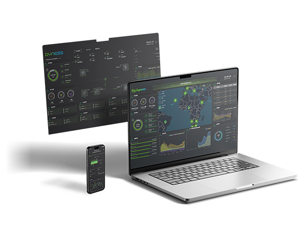











LFP Battery Storage Solutions: Why LFP Is the Right Choice


Get notified about new updates, products, tips and tutorials. No spam.
The choice of battery chemistry plays a critical role in the safety, durability, and long-term performance of energy storage systems. Lithium iron phosphate (LFP), also known as LiFePO4, has become an important choice for stationary battery storage because of its thermal stability and suitability for repeated charging and discharging. During operation, lithium ions move between the electrodes, while the phosphate-based crystalline structure contributes to the material's thermal stability. For energy storage projects, LFP offers a practical balance between chemical stability and operational requirements, although its lower energy density per unit of mass or volume may be a consideration for space-constrained installations.

Understanding LFP System Architecture
Choosing LFP Battery Storage Solutions involves evaluating more than the cell chemistry itself. A complete battery system consists of individual cells, battery packs, and supporting equipment responsible for energy conversion, monitoring, and protection. Each component performs a different function in maintaining reliable operation. The cell stores energy, the battery pack organizes and connects the cells, while the surrounding system manages electrical performance and operating conditions. For stationary applications, the overall design must balance cycling requirements, temperature management, installation space, and maintainability. Understanding these different layers helps buyers assess the actual engineering quality behind a LiFePO4 battery storage system rather than relying solely on its chemistry designation.

Thermal Management & Temperature Control
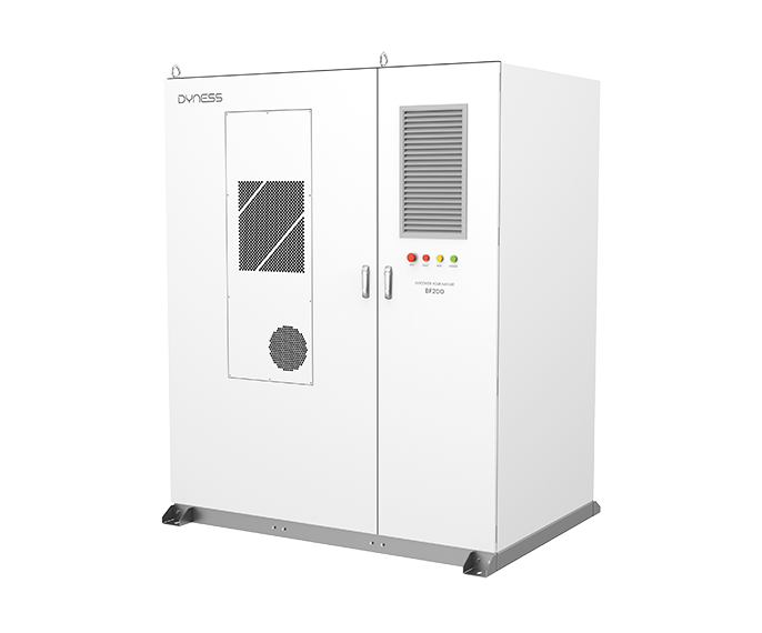
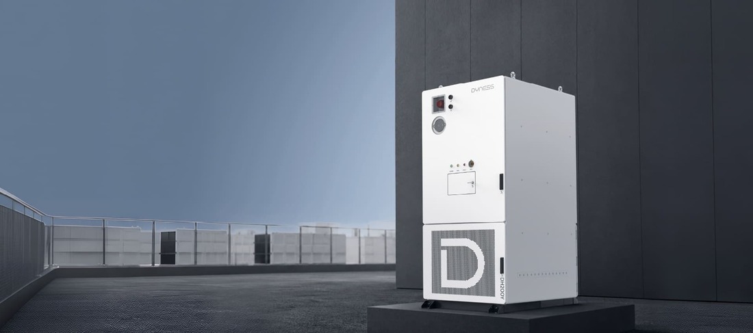
Effective thermal management is essential for maintaining battery performance and limiting the impact of localized overheating. Cooling systems regulate operating temperatures, temperature sensors detect abnormal changes, and thermal insulation helps restrict heat transfer between adjacent cells. These functions work together but serve different protective purposes. The Dyness DH200Y-C260 combines PACK-level liquid cooling with PCS air cooling, maintaining the stated battery-pack temperature difference within ≤3°C. This specification describes temperature uniformity across the battery pack rather than an absolute operating temperature. By combining thermal management with appropriate monitoring and insulation measures, Dyness energy storage solutions provide a structured approach to managing temperature variations during operation.
Multi-Layered Safety Protection & Fault Management
Battery safety requires multiple protective mechanisms with clearly defined functions and activation conditions. Dyness metal battery packs incorporate pressure-release valves alongside fire-suppression equipment. The pressure-release valve activates when internal pressure reaches its preset threshold, while the suppression system responds to a separate temperature trigger. At the cabinet level, gas venting and internal fire suppression provide additional protection, supported by external firefighting provisions when necessary. System-level monitoring further strengthens operational safety by identifying abnormal battery conditions through equipment status and operating data. Combined with the Battery Management System (BMS) and protective equipment, these mechanisms support fault detection and isolation, helping limit the potential impact of abnormal operating conditions.
Testing Validation, Cycle Life & Warranty
Technical validation and lifecycle specifications provide important evidence when evaluating LFP Battery Storage Solutions. Dyness validation includes environmental testing from −30°C to 70°C, induced thermal-runaway tests, propagation-control checks, and pressure-release testing. These tests examine specific safety and environmental performance characteristics; the tested temperature range should not be interpreted as the approved operating temperature range of every product. Lifecycle figures also require model-specific evaluation. The Dyness solution portfolio includes battery-cell cycle lives of up to 8,000 cycles and performance-guarantee periods of up to 10 years, depending on the applicable product and operating conditions. Cycle life cannot be directly converted into calendar years, and maximum portfolio specifications should not be assumed to apply identically to every model.
Conclusion
LFP is a practical choice for energy storage applications that prioritize thermal stability, repeated cycling, and long-term operational reliability. However, battery safety depends on more than cell chemistry alone. Effective thermal management, insulation, pressure relief, fire suppression, system monitoring, and model-specific validation all contribute to the overall protection architecture. At Dyness, we integrate these engineering considerations into our energy storage solutions to support reliable residential and commercial applications. Evaluating each protective layer alongside its defined operating conditions helps customers and project developers make more informed decisions when selecting long-term battery storage systems.
FAQ
-
Q: Does Dyness product certification mean any installer can install the system?

A: No. Product certification does not replace installer qualification. The installation still needs to follow local electrical regulations, grid requirements, product documentation, and approved system configuration.
-
Q: What architecture do Dyness DH200F, DH200Y, and DH800Y series products use?
A: The full range adopts a distributed modular architecture. The hardware consists of independent battery-cluster distributed units, supporting DC-side multi-cluster parallel connection and incremental expansion. The software is equipped with a distributed coordinated control system, enabling decentralized operation, intelligent multi-cluster coordination, and independent fault isolation. This is the standardized core architecture of Dyness C&I energy storage.
-
Q: What is the most fundamental difference between centralized and distributed architectures?
A: The most fundamental difference lies in how battery clusters are connected with the PCS. In centralized architecture, multiple battery clusters are connected in parallel on the DC side and share one high-power PCS for unified inversion. In distributed architecture, each battery cluster is equipped with an independent small PCS, and AC-side parallel connection is used for energy aggregation. This determines that the former is based on “unified control and scale priority,” while the latter is based on “decentralized autonomy and refined management.”
Learn More